You probably never think about the machinery moving fluid until something breaks. Then you realize that without pumps, civilization stops. They are simple devices in concept: spend energy, move liquid. But the engineering required to do it efficiently? That’s a complex, gritty history of mining, physics, and materials science.
The earliest versions were brute force. Think Persian and Roman waterwheels. Or the Archimedes screw. You spin it, water goes up. Simple. But as Middle Ages mining operations dug deeper, simple wheels weren’t enough. They needed suction pumps.
Georgius Agricola described these in De re metallica back in 1556. The principle relies on atmospheric pressure. Raise a piston. Create a partial vacuum. Air pressure outside pushes water into the cylinder. It’s a neat trick. Until you hit a hard limit.
Atmospheric pressure can only push water up about 34 feet (10 meters). Try to suck water from a mine shaft deeper than that? It won’t work. The vacuum fails. So engineers invented the force pump. Now the downward stroke of the piston physically forces water out through a side valve. The height depends on the force you apply, not just the air pressure.
Classification of Pumps
How do we categorize this chaos? It comes down to energy transfer. There are three basic ways to move fluid:
- Volumetric displacement. Moving a chunk of fluid from point A to point B.
- Kinetic energy. Spinning the fluid fast or hitting it with an impulse.
- Electromagnetic force. Using magnetic fields to push conductive fluids. This one requires the fluid to be a good electrical conductor.
If you are moving gas, you’re probably talking about compressors, blowers, or fans. If you are mechanically displacing fluid, it’s a positive displacement pump. If you are using a rotating impeller to add speed, it’s a kinetic pump.
There is a general rule of thumb here. Positive displacement pumps handle low volumes at high pressure. Kinetic pumps handle high volumes at low pressure. It’s a trade-off. You can’t have both without specialized engineering.
There is a catch. You need a certain amount of inlet pressure just to get the fluid to flow into the pump. If that pressure is too low, you get cavitation. This is the formation of vacuous spaces where liquid should be. Vapor bubbles form in the suction line. They travel into the pump. They hit a region of higher pressure. They collapse.
The result? Excessive noise. Vibration. Corrosion. Erosion. The pump eats itself from the inside out.
Pump efficiency isn’t static. It depends on the fluid. Mobile liquids like water pump efficiently. Viscous fluids like molasses? Not so much. Viscosity decreases as temperature rises. That’s why industrial plants often heat thick liquids before pumping them. It’s a practical hack. Heat it up. It flows better.
Positive Displacement Pumps
These pumps lift a given volume for every cycle. They are reliable workhorses. Divided into two main classes: reciprocating and rotary.
Reciprocating includes piston, plunger, and diaphragm types. Rotary includes gear, lobe, screw, vane, and cam pumps.
The plunger pump is the oldest common type. It consists of a cylinder. A piston or plunger moves back and forth. In a plunger pump, the seal is stationary. The plunger pushes into the fluid. In a piston pump, the seal moves with the piston.
As the piston moves outward, the volume in the cylinder increases. Fluid enters through a one-way inlet valve. As it moves inward, the volume decreases. Pressure spikes. Fluid is forced out the outlet valve.
The pumping rate isn’t constant. It hits zero when the piston changes direction. It peaks halfway through the stroke. To smooth this out, you can use both sides of the piston. Double-acting pumps. Or you can add more cylinders.
You can vary the rate by changing the reciprocating speed of the piston rod. Or by changing the stroke length. The piston can be driven directly by steam, compressed air, or hydraulic oil. Or through a mechanical linkage that turns rotary motion into reciprocating motion.
These pumps are expensive. But they are durable. Piston pumps have run for over 100 years without repair or replacement. That’s not a typo. A century of service.
Diaphragm pumps work similarly but replace the piston with a pulsating flexible diaphragm. No packings in contact with the fluid. This solves a specific problem. Leaks. If you are pumping toxic, corrosive, or expensive chemicals, you can’t afford a leak through packing. The diaphragm keeps everything sealed inside.
Fluid enters and leaves through check valves. The diaphragm can be actuated mechanically or by a fluid like compressed air or oil.
They deliver a pulsating output. Liquids. Gases. Mixtures. They are useful for liquids containing solid particles. And they can run dry for extended periods. You can also change the pumping rate while the machine is running.
How external gear pumps actually move fluid
Most people assume pumps are magic boxes that suck things up and spit them out. They aren’t. They are just mechanical traps. The external gear pump—the workhorse of industrial fluid handling—relies on a surprisingly simple trick.
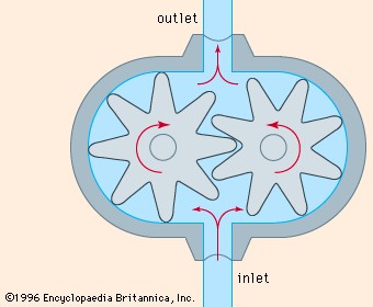
One gear turns. It is driven by a motor or engine. The other gear just sits there and lets itself be pushed. It runs free.
Here is where the physics get interesting. As those teeth rotate away from each other, they create a void. A partial vacuum. Nature hates a vacuum, so it rushes in to fill the gap. Fluid gets sucked into that space between the teeth and the casing.
But the trap doesn’t stay open forever.
The gears mesh back together. The teeth lock. The fluid has nowhere to go but out. The pressure spikes. It forces the liquid into the discharge line.
Think about the directionality. You can reverse the rotation. If you spin the gears the other way, the intake and outlet swap places. The pump discharges in either direction, depending entirely on which way the motor turns.
It is efficient. It is robust. But it is also basic.
A partial vacuum, created by the unmeshing of the rotating gears, draws fluid into the pump.
This mechanism is why gear pumps are everywhere. They move thick oils. They move fuels. They move chemicals that would destroy a more delicate impeller.
The casing is fixed. It does not move. The teeth move inside it. The fluid travels from one side to the other, trapped in the pockets between the teeth and the wall. It is a continuous loop.
There is no pulsing. No vibration. Just steady, rhythmic pressure.
Why does this matter? Because when you need to move something that doesn’t want to move—a heavy sludge, a viscous grease, a thick polymer—you need positive displacement. You need to physically shove the molecule forward.
Gear pumps do exactly that. They catch the fluid. They hold it. They throw it out the other side.
Simple. Brutal. Effective.
The design has barely changed in a century. That is not a sign of stagnation. It is a sign of perfection.
Or close enough.
Once the fluid leaves the mesh point, it is under pressure. High pressure. Enough to push through narrow pipes. Enough to overcome resistance.
You can reverse the flow. You can change the direction of the discharge. Just flip the rotation.
That is the beauty of it. One motor. Two gears. A closed loop.
It works until it doesn’t. Wear and tear eventually loosen the tolerances. The gap between the teeth and the casing grows. Efficiency drops. The pump still moves fluid, but less of it.
But that is a problem for tomorrow.
For now, the gears turn. The vacuum forms. The fluid moves.
And we don’t even have to think about it.
Internal Gear Mechanics and Limitations
Look at the internal gear pump in Figure 2. It’s a clever bit of machinery. The driven gear is a rotor with teeth cut into its inner circumference. These teeth mesh with an idler gear that has external teeth. The idler sits off-center. This offset creates the pumping action. A fixed casing part called the crescent splits the flow. It separates the idler gear from the rotor.
This design handles liquids with trapped vapours or gases well. But there is a catch. The pump relies on the liquid itself to lubricate the moving parts inside. Pump pure gas? The gears grind against each other without that protective film. They wear out fast. So, gases are out.
For liquids, the output is steady. Negligible pulsations. If you keep the rotor speed constant, you get a constant flow. But wear and tear change the game. Erosion and corrosion widen the gaps between the gears. Liquid slips back through these gaps instead of moving forward. Efficiency drops.
Internal gear pumps require the fluid to provide lubrication, making them unsuitable for pumping gases.
Clogging is the other enemy. Solid particles jam the tight clearances. You cannot run these pumps with slurries or debris-heavy fluids. However, they do not need check valves. This simplicity allows them to handle very viscous liquids. Thick oils? No problem.
Lobe Pumps and Compressors
Lobe pumps look like cousins to external gear pumps. They share the same basic shape. But the rotors are different. Instead of gears, they have lobes. Two, three, or four lobes. The key difference is how they move. Both rotors are driven. They are not meshed together like gears.
This design means more pulsation in the output. External gear pumps are smoother. Lobe pumps are rougher on the flow. But they take less wear. The rotors do not touch. There is no metal-to-metal contact. This makes them durable for abrasive materials, though less efficient at flow stability.
Lobe-type compressors use this same principle. They pump gas. Each rotor has two lobes. They move air or gas where gear pumps would fail due to lack of lubrication.
The Screw Pump Principle
Screw pumps work differently. A helical screw rotor spins inside a fixed casing. The casing is shaped to form cavities. As the screw turns, these cavities move from the intake to the discharge.
When a cavity forms at the intake, it creates a partial vacuum. This vacuum sucks fluid into the pump. The fluid travels inside that progressing cavity. It does not splash around. It moves in a straight line.
At the discharge end, the casing narrows. The cavity closes. This closure increases pressure. The pressure forces the fluid into the outlet line. It is a positive displacement method.
Screw pumps create a steady flow by trapping fluid in progressing cavities that move axially through the pump.
These pumps are versatile. They handle liquids with vapours. They also handle solid particles. The helical design allows debris to pass without jamming. The output is steady. Negligible pulsations for a given rotor speed.
They do not need inlet or outlet check valves. This makes them ideal for viscous liquids. Thick substances slide through easily. No extra valves to clog.
Cost and Longevity Trade-offs
Screw pumps are not cheap. They are
The sliding vane pump, as seen in Figure 3, relies on a simple but clever mechanical arrangement. The rotor sits off-center inside the casing. Rectangular vanes are tucked into slots along the rotor’s edge. When the motor spins the rotor, centrifugal force pushes the vanes outward. They press hard against the curved inner wall of the fixed casing. This creates a tight seal.
As the rotor turns, it creates a partial vacuum on the suction side. Fluid rushes in to fill that void. The rotating vanes trap pockets of liquid between the rotor and the casing. They carry this fluid around to the discharge side. There, the space shrinks. Pressure builds. The fluid is forced out into the outlet line.
How to Adjust Flow Rate
You can control the pumping rate by adjusting the eccentricity. This means changing how far off-center the rotor sits. Move it, and you change the volume swept by the vanes. The design is self-compensating for wear. The vanes slide in and out as they wear down. They stay in contact with the casing. Pumping capacity doesn’t drop until the vanes are badly worn.
These pumps are robust. They deliver constant output with negligible pulsations at any given speed. You don’t need inlet or outlet check valves. That simplifies the system. They handle liquids mixed with vapors or gases well. But they fail with solids. If your fluid has particles, don’t use a vane pump. The vanes will jam or wear out instantly.
Vane-type compressors exist too, but they pump gases, not liquids.
The Shift to Kinetic Pumps
Kinetic pumps work on a different principle. They impart velocity to the fluid first. Then, they convert that kinetic energy into pressure head. Most of the speed becomes static pressure. This class includes centrifugal and regenerative pumps.
Centrifugal pumps have been around since about 1680. For centuries, they were little used. Why? The technology wasn’t quite there. It took until the 20th century for kinetic pumps to become common. The materials and manufacturing precision needed to handle high speeds efficiently finally arrived. Today, they dominate large-scale fluid movement.
The difference is fundamental. Vane pumps trap discrete volumes of fluid. Kinetic pumps accelerate a continuous stream. One is positive displacement. The other is dynamic. Both have their place. But if you’re moving water through a city, you’re likely using a kinetic pump. If you’re metering oil in a small machine, you might use a vane pump.
The history of pumps is a history of efficiency. We moved from trapping fluid to throwing it. From mechanical seals to aerodynamic blades. The sliding vane pump remains useful. Its simplicity is its strength. But the kinetic pump’s scalability changed industry. We stopped building smaller and stronger. We started building faster and larger.
There’s a reason we still use vanes in some applications. Reliability matters. But the future belongs to those who can move more fluid with less energy. The kinetic pump does that. It’s not just about pressure. It’s about momentum. And momentum is hard to beat when you’re moving millions of gallons.
The Standard Centrifugal Pump
You probably won’t notice them, but radial flow pumps are doing the heavy lifting in everything from your home water supply to industrial cooling systems. Specifically, the volute pump dominates this category. It’s the workhorse you want to know about.
Fluid enters the impeller near its center. The impeller spins at high speed. This throws the fluid outward against the pump casing. The result is a partial vacuum. That vacuum pulls in more fluid. The cycle continues.
Why Volute Pumps Win
These units are robust. They are also relatively inexpensive to produce. If you need quiet operation and dependability, this is a solid pick. Performance remains steady even when corrosion and erosion try to take their toll.
The construction is simple. Compactness matters in tight spaces. You don’t need inlet or outlet check valves. That simplifies the piping. It reduces potential failure points.
Volute centrifugal pumps are robust, quiet, and dependable, with performance largely unaffected by corrosion and erosion.
When They Struggle
They aren’t perfect. They can handle liquids with solid particles. But introduce too much vapor into the mix. The suction breaks. Cavitation follows. That’s bad for longevity.
Viscosity is another enemy. These pumps operate best with nonviscous liquids. Pump something thick. You’ll see capacity drop significantly.
The Diffuser Alternative
Not all radial flow pumps use a volute casing. There’s the diffuser pump. It takes a different approach after the fluid leaves the impeller.
The fluid passes through a ring of fixed vanes. These vanes diffuse the liquid. They provide controlled flow. More importantly, they convert velocity head into pressure head more efficiently.
It’s about efficiency. The volute is simple. The diffuser is optimized. Choose based on what your process demands.
Axial and Mixed Flow Mechanics
The rotor in an axial flow centrifugal pump is essentially a propeller. Fluid moves parallel to the axis, as shown in Figure 5. Diffusion vanes sit in the discharge port. They kill the rotational velocity the propeller gave the fluid. Axial flow compressors also move gases using this same principle.
Mixed flow pumps take a different path. Fluid exits both radially and axially. It enters a volute-type casing. The geometry changes the direction and pressure simultaneously.
Regenerative Pump Dynamics
A regenerative pump is also known as a turbine pump or peripheral pump. The impeller features vanes on both sides of its rim. It rotates inside a ringlike channel within the casing.
Fluid does not shoot out from the impeller tip freely. Instead, it recirculates back to a lower point on the impeller diameter. This process is called regeneration. It boosts the head developed by the pump.
Clearances in these pumps are tight. You cannot use them for liquids with solid particles. Solids would jam the mechanism. They handle liquids with vapours and gases. They can even pump gases if there is enough liquid to seal the close clearances. They are strictly for mobile liquids.
Electromagnetic Pump Principles
Electromagnetic pumps have one major limitation. They only work with fluids that conduct electricity well. The pipe carrying the fluid sits in a magnetic field. A current passes crosswise through the fluid. This creates an electromagnetic force. The force pushes the fluid in the direction of flow.
The current and field can be generated in various ways. The principle matches that of an electric motor. These pumps are critical for cooling nuclear reactors. They move liquid metals efficiently without moving mechanical parts in the fluid stream.
Gas lifts operate without a single moving part. Compressed gas hits the liquid at the well’s bottom. The mixture becomes lighter. Buoyancy takes over. It rises and dumps out. This design handles solids easily. Once common for water and oil, air lifts are now rare.
The Jet Ejector Principle
Fluid moves through a venturi nozzle. Velocity spikes. Pressure drops. This creates suction. A second fluid stream gets entrained.
Aspirators use water for this. Steam ejectors push vapors. They handle large volumes at low pressures. High-velocity steam enters the pump. It transfers momentum to the gas. The mixture hits the diffuser. Kinetic energy turns into pressure. Gas moves from low to high pressure. These pumps date back to 1850.
Hydraulic Rams and Water Hammers
A downward flow of water lifts some of it higher. The inlet pipe sees a check valve close. Kinetic energy stops suddenly. Like a water hammer. Pressure spikes. A second valve opens. Water enters the air chamber. It pushes up the discharge pipe.
Pressure in the inlet drops. The first valve reopens. Compressed air seals the chamber. The cycle repeats. About 15 percent of the inlet water reaches five times its fall height. Developed in the late 18th century, these still power some domestic systems.
Creating a Vacuum
Vacuum pumps are compressors. They intake gas below atmospheric pressure. They compress it. They discharge at atmospheric pressure. Low-pressure gas has large volume. These pumps are bulky.
Steam jet ejectors dominate industry. Reciprocating pistons work too. Rotary-vane pumps are common. All serve to pull air out.